1. Introduction
The air supply sub-system is a critical part of a vehicle’s air brake system, responsible for providing and maintaining the compressed air necessary for braking operations.
Function:
- The air supply sub-system generates, stores, and manages compressed air, which is used to power the brake actuators.
- It regulates the air pressure, removes moisture and contaminants, and provides warnings when air pressure is dangerously low.
Components Overview:
The air supply sub-system consists of various interconnected components that work together to generate and maintain the necessary air pressure. These components include:
- Air Compressor: Generates compressed air.
- Governor: Regulates the air compressor’s operation.
- Air Tanks: Store compressed air.
- Air Dryer: Removes moisture from the air.
- Alcohol Evaporator: Prevents freezing in the air brake system.
- Air Pressure Gauge: Monitors the air pressure levels.
- Safety Valve: Prevents overpressure.
- Low Air-Pressure Warning Devices: Alerts the driver when air pressure is too low.
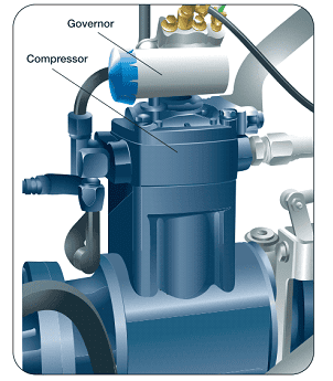
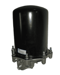
2. Air Compressor
- The air compressor is the heart of the air brake system, generating the compressed air required for the brakes to function.
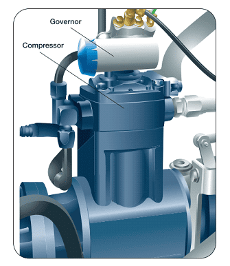
Function:
The primary function of the air compressor is to force air into a smaller space, thereby increasing its pressure. This compressed air is then stored in the air tanks and used by the brake system to apply the brakes.
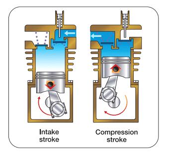
The process of compressing air involves two main strokes: the intake stroke and the compression stroke.
- Intake Stroke: During the intake stroke, the compressor piston moves down, allowing atmospheric air to enter the cylinder through the intake valve.
- Compression Stroke: As the piston moves up, it compresses the air, which is then forced out through the discharge valve into the air storage tanks.
Normal Operating Pressure Range:
- The normal operating pressure range for an air brake system is between 552 kPa (80 psi) and 932 kPa (135 psi).
- Maintaining the air pressure within this range is crucial for the safe and effective operation of the brake system. Pressures outside of this range can lead to brake system failure or reduced braking efficiency.
Powering the Air Compressor:
- Direct Drive: In some systems, the air compressor is powered directly by the engine. This means that the compressor is mechanically connected to the engine’s crankshaft, providing a direct and efficient transfer of power.
- Belt Drive: Alternatively, the air compressor can be powered using belts and pulleys. In this setup, a belt connected to the engine’s crankshaft drives the compressor’s pulley, which in turn powers the compressor.
Mounting Options:
- Direct Mountinge: The air compressor can be mounted directly onto the engine. This method provides a compact and efficient setup, reducing the need for additional mounting hardware and simplifying the drive mechanism.
- Bracket and Fastener Mounting: The compressor can also be mounted using brackets and fasteners. This method allows for more flexibility in the positioning of the compressor, making it easier to fit into different engine compartments and vehicle designs.
Preventing Overheating:
Overheating can significantly reduce the efficiency and lifespan of the air compressor. To prevent overheating:
- Adequate Ventilation: Some compressors are equipped with cooling systems, such as water jackets or air-cooled fins, to help regulate temperature.
- Cooling Systems: Some compressors are equipped with cooling systems, such as water jackets or air-cooled fins, to help regulate temperature.
- Regular Maintenance: Regularly check and maintain the compressor’s components to ensure they are functioning correctly. This includes monitoring oil levels in lubricated compressors and inspecting belts and pulleys.
- Operating within Limits: Avoid overworking the compressor by ensuring it operates within the specified pressure and duty cycle limits.
Types of Air Compressors:
- Single Cylinder Compressors: These compressors have one cylinder and are typically used in smaller or less demanding applications.
- Dual Cylinder Compressors: These compressors have two cylinders and are used in larger vehicles or applications requiring more air volume.
Maintenance and Care:
- Regular maintenance of the air compressor is crucial for ensuring its longevity and reliability. This includes checking for leaks, ensuring the belts are in good condition, and verifying that all mounting hardware is secure.
- It is also important to monitor the compressor’s performance, such as its ability to build pressure within the specified time and its operating temperature.
3. Governor
The governor is a critical component of the air brake system, responsible for regulating the air compressor’s operation to maintain safe and effective air pressure levels.
Function:
- The primary function of the governor is to control the cut-in and cut-out pressure of the air compressor. This regulation ensures that the air compressor activates and deactivates at the appropriate pressure levels, maintaining the system’s efficiency and safety.
- Cut-In Pressure: The pressure at which the governor activates the air compressor to start building pressure. Typically, this occurs when the air pressure drops to around 552 kPa (80 psi).
- Cut-Out Pressure: The pressure at which the governor deactivates the air compressor to stop building pressure. This usually happens when the air pressure reaches approximately 932 kPa (135 psi).
Safe Operating Pressure Range:
- The governor ensures that the air brake system operates within the safe pressure range of 552 kPa (80 psi) to 932 kPa (135 psi).
- Operating within this range is crucial for the safety and efficiency of the braking system. Pressures below this range can lead to inadequate braking force, while pressures above this range can cause system components to fail or become damaged.
Safety Implications:
- The governor plays a vital role in preventing the compressor from running continuously, which could lead to overheating and excessive wear.
- It also prevents the air system from reaching dangerously high pressures, which could cause failures in other components of the air brake system.
4. Air Pressure Build-Up Time in Air Brake Systems
Introduction:
- Air pressure build-up time is a critical measure in air brake systems, referring to the time it takes for the system to build up sufficient air pressure to be operational after the engine is started.
Importance of Air Pressure Build-Up Time:
- Safety: Adequate air pressure is essential for effective braking. If the pressure build-up time is too long, the vehicle may not be safe to operate.
- Regulations: There are regulatory standards that dictate the maximum allowable build-up time to ensure that air brake systems are functioning properly before a vehicle can be driven.
Standard Build-Up Time:
- Dual Air Systems: Typically, the air pressure in the brake system should build up from 85 psi to 100 psi within 45 seconds in a dual air system for most heavy-duty vehicles. This standard ensures that the brake system reaches a safe operating pressure quickly, minimizing delays and ensuring that the vehicle is ready for operation.
- Single Air Systems: For vehicles built before 1975 with a single air brake system, the requirement is for the air pressure to build up from 50 psi to 90 psi within 3 minutes, with the engine operating at 1200 rpm.
Factors Affecting Build-Up Time:
Condition of the Air Compressor:
- The efficiency and condition of the air compressor significantly impact the build-up time. A well-maintained compressor with no leaks or wear will build pressure more quickly.
Air Leaks:
- Leaks in the air lines, tanks, or other components can cause slow pressure build-up. Regular inspection and maintenance are necessary to identify and fix leaks.
Air Dryer and Filters:
- Clogged air dryers or filters can restrict airflow, increasing the time it takes to build pressure. Keeping these components clean and in good working order is essential.
Ambient Temperature:
- Cold temperatures can increase the build-up time as the air compressor works harder to compress cold, dense air. Using proper lubricants and keeping the system well-maintained can help mitigate this.
System Design:
- The design and capacity of the air brake system, including the size and number of air tanks, also affect build-up time. Larger systems may take longer to build pressure.
Monitoring and Testing:
- Regular Testing:: Drivers should regularly test the air pressure build-up time during pre-trip inspections to ensure the system is operating within acceptable limits.
- Pressure Gauge: Monitoring the air pressure gauge helps drivers ensure that the pressure build-up is happening within the specified time frame.
5. Air Tanks
Introduction:
- Air tanks are essential components of a vehicle’s air brake system, serving as reservoirs for the compressed air generated by the air compressor.
- Proper maintenance of these tanks is crucial to ensure reliable and efficient brake system operation.
Types of Air Tanks:
- Supply (Wet) Tank
- Primary and Secondary Tanks
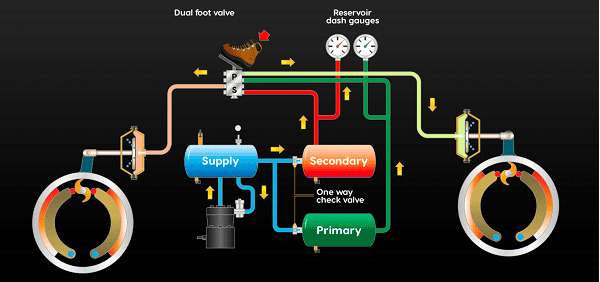
Supply (Wet) Tank
Function
- The supply tank, also known as the wet tank, is the first tank to receive compressed air from the air compressor.
- It is referred to as the “wet” tank because it collects most of the moisture and oil from the compressed air, acting as a primary filter to protect the rest of the air system.
Importance
- By capturing moisture and oil early in the system, the supply tank helps to prevent these contaminants from reaching the primary and secondary tanks, which can lead to corrosion, freezing, and reduced efficiency.
Maintenance
Regular draining of the supply tank is essential to remove accumulated moisture and oil. This prevents the formation of sludge and ensures the system remains clean and functional.
Draining Procedures
- Locate the drain valve at the bottom of the supply tank
- Open the valve to release the collected moisture and oil. This should be done daily or according to the vehicle manufacturer’s recommendations.
Primary and Secondary (Dry) Tanks
Function
- The supply tank, also known as the wet tank, is the first tank to receive compressed air from the air compressor.
- It is referred to as the “wet” tank because it collects most of the moisture and oil from the compressed air, acting as a primary filter to protect the rest of the air system.
Primary Tank
- Typically supplies air to the rear brakes.
- Provides a reservoir of compressed air that is essential for the operation of the rear braking system.
Secondary Tank
- Typically supplies air to the front brakes or other systems such as auxiliary functions.
- Ensures that the front brakes or other air-operated components have a dedicated supply of compressed air.
Importance
- These tanks ensure that even if the supply tank has issues, the air brake system will still have sufficient air for safe operation.
- They provide redundancy and improve the reliability of the air brake system.
Maintenance
- Regular draining of both the primary and secondary tanks is necessary to remove any residual moisture and oil that might have passed through the supply tank.
- Inspect the tanks periodically for pressure levels and signs of corrosion or damage.
6. Moisture, Sludge, and Draining Procedures
Moisture and Oil Collection
- As air is compressed, moisture and oil in the air condense and accumulate in the air tanks, especially in the supply (wet) tank.
- Over time, sludge (a mixture of water, oil, and contaminants) can form at the bottom of the tanks.
- If not regularly removed, moisture and sludge can lead to corrosion, freezing in cold temperatures, and contamination of the air brake system.
Draining Procedures:
Importance of Draining:
- Regular draining of air tanks is crucial to remove accumulated moisture and oil, preventing damage and ensuring the reliability of the air brake system.
Draining the Supply (Wet) Tank First:
- The supply tank should be drained first because it collects the most moisture and oil.
- Locate the drain valve at the bottom of the supply tank and open it to release the accumulated moisture and oil.
Periodically Draining All Air Tanks:
- All air tanks should be drained periodically according to the vehicle manufacturer’s recommendations to ensure no moisture or oil is left to accumulate and cause issues.
- This includes opening the drain valves on all tanks, starting with the supply tank, followed by the primary and secondary tanks.
Types of Drains:
- Manual Drains: Require manual operation to release collected moisture and oil.
- Automatic Drains: Automatically expel moisture and oil at regular intervals or when the compressor reaches cut-out pressure, reducing the need for manual intervention.
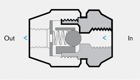
7. One-Way Check Valves
Function
- One-way check valves are installed between the air tanks to prevent air from flowing back to the supply tank or the compressor.
- These valves ensure that once the air is in the primary and secondary tanks, it stays there, maintaining the necessary pressure for the brake system.
Importance
- These valves help isolate any leaks and maintain pressure in the air tanks, ensuring the system remains operational even if one part fails.
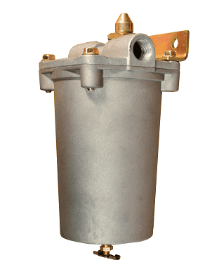
8. Air Dryer
Function
- The air dryer is a critical component of the air brake system, designed to remove moisture from the compressed air before it reaches the air tanks and other parts of the brake system.
- Removing moisture is essential to prevent freezing and corrosion, which can impair the performance and safety of the braking system.
Operation
- As compressed air flows from the compressor, it passes through the air dryer.
- The air dryer typically contains a desiccant material that absorbs moisture from the air.
- When the air compressor reaches cut-out pressure, the air dryer expels the collected moisture.
Maintenance
- Regular inspection and maintenance of the air dryer are necessary to ensure it functions effectively
- The desiccant material should be replaced periodically according to the manufacturer’s recommendations.
9. Alcohol Evaporator
Function
- The alcohol evaporator adds alcohol vapor to the compressed air in the brake system to prevent freezing of any moisture that remains after the air dryer.
- It introduces a controlled amount of alcohol vapor into the air stream, which lowers the freezing point of any remaining moisture.
Benefits
- Prevents ice formation in the air brake system, ensuring reliable operation even in sub-zero temperatures.
- Helps to protect the air brake components from freeze-related damage and potential failure.
Maintenance
- The alcohol evaporator should be checked regularly to ensure it is functioning properly.
- The alcohol reservoir should be kept filled with the appropriate type of alcohol, as specified by the manufacturer.
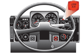
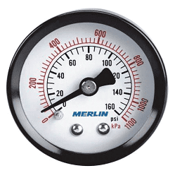
10. Air Pressure Gauge
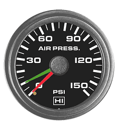
Introduction
- The air pressure gauge is a vital instrument in the vehicle’s air brake system, providing real-time information about the air pressure levels in the primary and secondary air tanks.
Function
- The primary function of the air pressure gauge is to indicate the pressure in the vehicle’s dual service air tanks (primary and secondary tanks).
- By displaying the current air pressure, the gauge helps the driver monitor the system and ensure it is operating within the normal pressure range.
Normal Pressure Range
- The normal operating pressure range for the air brake system is typically between 552 kPa (80 psi) and 932 kPa (135 psi).
- Maintaining air pressure within this range is crucial for the safe and effective operation of the brake system. Pressures below this range can result in inadequate braking force, while pressures above this range can lead to component damage or failure.
Importance of Monitoring
- Safety: Monitoring the air pressure gauge allows the driver to take immediate action if the pressure falls outside the normal range, preventing potential brake failure and ensuring safe vehicle operation.
- Pre-Trip Inspections: Regularly checking the air pressure gauge during pre-trip inspections helps ensure that the air brake system is functioning correctly before starting a journey.
- Real-Time Monitoring: During operation, continuous monitoring of the air pressure gauge provides assurance that the brake system is maintaining the necessary pressure for optimal performance.
Types of Air Pressure Gauges
- Analog Gauges: Traditional air pressure gauges with a needle that moves to indicate the pressure level. These are commonly found in many commercial vehicles.
- Digital Gauges: Modern air pressure gauges that provide a digital readout of the pressure levels. These can offer greater precision and are easier to read at a glance.
Placement
- The air pressure gauge is typically located on the vehicle’s dashboard, within easy view of the driver. This placement ensures that the driver can quickly and easily monitor the air pressure while driving.
11. Safety Valve
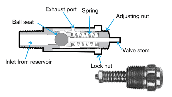
Introduction
- The safety valve is a crucial component of the air brake system, designed to prevent overpressure, which can cause damage to the system and reduce braking efficiency.
Function
- The primary function of the safety valve is to release excess air pressure from the system if it exceeds a predetermined level, typically around 150 psi (1034 kPa).
- This ensures that the air brake system operates within safe pressure limits, protecting components from potential damage due to overpressure.
Importance
- System Protection: By preventing overpressure, the safety valve protects the air tanks, lines, and other components from excessive stress and possible failure.
- Safety: Maintaining appropriate air pressure levels is critical for the reliable operation of the air brake system, ensuring that the vehicle can be safely controlled and stopped.
Operation
- The safety valve is typically spring-loaded and set to open at a specific pressure threshold.
- When the air pressure exceeds this threshold, the valve opens, allowing excess air to escape and reducing the system pressure to safe levels.
Maintenance
- Regular inspection of the safety valve is essential to ensure it functions correctly.
- If the valve fails to open at the set pressure, it should be replaced or adjusted according to manufacturer specifications.
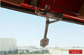
12. Low Air-Pressure Warning Devices
Introduction:
- Low air-pressure warning devices are essential for alerting the driver to dangerously low air pressure levels in the air brake system, ensuring timely corrective action can be taken.
Function:
- These devices provide both audible and visual warnings when the air pressure in the system drops below a safe threshold, typically around 60 psi (414 kPa).
- The warnings are designed to catch the driver’s attention immediately, prompting them to address the low pressure before it affects the braking performance.
Types of Warnings:
- Audible Warnings: Usually in the form of a buzzer or alarm, the audible warning is loud enough to be heard over the engine noise, ensuring the driver is aware of the low pressure situation.
- Visual Warnings: Typically, a warning light or indicator on the dashboard illuminates when the air pressure drops below the safe level, providing a clear visual cue to the driver.
Importance
- Safety: Low air-pressure warnings are critical for preventing brake failure, as inadequate air pressure can result in insufficient braking force, leading to dangerous driving conditions.
- Prompt Action: These warnings ensure that drivers can take immediate action, such as stopping the vehicle and checking for leaks or other issues causing the low pressure.
Maintenance:
- Regularly test the low air-pressure warning devices to ensure they function correctly.
- If the audible or visual warnings do not activate at the specified pressure threshold, the devices should be inspected and repaired or replaced as necessary.
13. Compressed Air Hazards
Introduction
- Compressed air is a powerful and essential component of the air brake system, providing the necessary force to operate the brakes. However, because it is a form of stored energy, it can also be hazardous if not handled properly.
Hazards of Compressed Air:
Stored Energy
- Compressed air is under high pressure, making it a significant source of stored energy. If not controlled correctly, it can cause serious injury or damage.
Potential for Explosions
- If the system is over-pressurized or if components fail, there can be a risk of explosions, which can lead to severe injuries.
Airborne Debris
- Compressed air can propel debris at high speeds, potentially causing injuries or damage to equipment.
Noise Hazards
- The release of compressed air can generate loud noises, which can cause hearing damage if proper protective equipment is not used.
Direct Path of Exhausting Air
- You must avoid being in the direct path of any exhausting compressed air. The force of the air can cause serious injury, and debris can be ejected at high speeds.