- Need Any Help: +1 647-760-5505 or
- info@trubicars.ca
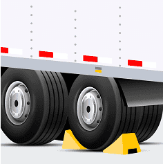
Before starting the inspection, make sure to secure the vehicle properly. Park your vehicle on level ground to prevent it from rolling. Apply the spring brakes and place wheel chocks or blocks around the wheels to secure the vehicle.
Important: Never leave the driver’s seat or get under the vehicle unless the spring brakes are applied or the wheels are securely blocked. This is crucial for your safety and the safety of those around you.
To ensure the low air-pressure warning device is functioning correctly, follow this detailed step-by-step procedure. This test requires reducing the pressure in the system until the warning device activates or the pressure reaches 55 psi (380 kPa), whichever is higher. Keep in mind that the pressure at which the warning device deactivates during a pressure increase may not be the same as the activation point during a pressure decrease.
Ensure Adequate Air Pressure:
|
 |
Prepare for the Test:
|
 |
Reduce Air Pressure:
|
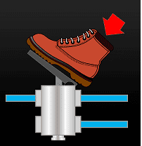 |
Monitor the Warning Device:
|
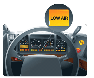 |
Evaluate the Warning Device Activation:
|
|


To ensure the air compressor can meet the demand of the air brake system and restore pressure quickly, you must test whether the air pressure rises to a specified level within a specified time. This test will help confirm the efficiency of the air compressor.
Prepare the Vehicle:
|
 |
Reduce System Pressure:
|
|
Set Engine Idle:
|
 |
Monitor Air Pressure:
|
 |
Record Pressure Build-Up Time:
|
|
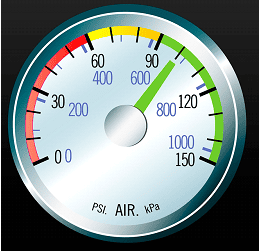
Air brake systems must operate with air pressure within a prescribed range. The system’s pressure range is controlled by the air-compressor governor settings, which determine when the air compressor will cut-out and cut-in. Drivers can perform a test to determine the settings and establish the normal operating pressure range for a particular vehicle.
The model year of a vehicle generally affects the governor pressure setting. Air brake system operating pressure ranges have increased over the past 20 years. Older systems may operate with lower pressure settings.
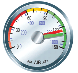
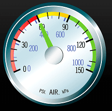
Air pressure gauges stop climbing with compressor cut-out. When a vehicle uses an air dryer, its exhaust cycle also indicates that the compressor has reached the cut-out setting. Observe the primary and secondary air-tank gauges to confirm when the pressure stops climbing and when the cut-out setting has been reached.
The cut-in pressure setting is normally 138 to 173 kPa (20 to 25 psi) below the cut-out pressure setting. Compressor cut-in causes a change in the sound of the engine and can be observed when the air-tank gauges begin to show an increase in pressure.
Cut-out and cut-in pressures should remain within the range specified by the vehicle manufacturer, and any change in these pressures, should be reported. Actual cut-out pressure must never be higher than 1000 kPa (145 psi). Actual cut-in pressure must never be less than 552 kPa (80 psi). The air brake system is defective when cut-out pressure is above 1000 kPa (145 psi) or cut-in pressure is below 552 kPa (80 psi).
| Properly secure the vehicle and release the spring brakes. | |
| Observe the primary and secondary air-tank pressure gauges | |
| Run the engine until air brake system pressure reaches its maximum level and note the cut-out pressure setting. |  |
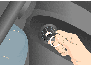
| Press and release the brake pedal several times to lower the system pressure and note the cut-in pressure setting. | 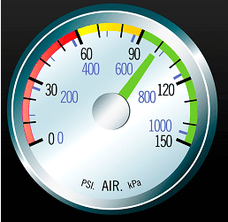 |
Drivers must be alert for air brake system leaks and pressure loss in the air tanks when brakes are not being used. These conditions indicate air loss in the air brake system. For safety, drivers should test the air-loss rate of the vehicle’s brake system.
To test the air-loss rate of the brake system, release the spring brakes, establish normal air pressure and shut off the engine. Hold the brake pedal in the fully applied position and observe the air-pressure readings for one minute.
The pressure will drop noticeably when the brakes are first applied, but must not continue to drop at a rate greater than specified in the chart below. The amount of pressure drop that takes place when brakes are first applied is not considered when performing the air- loss rate test. The air brake system is defective when air loss exceeds the specified values.
| Properly secure the vehicle and release the spring brakes. | 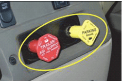 |
| Ensure that the air brake system is within its normal operating pressure range. Shut off the engine. |  |
| Press and hold the brake pedal in the fully applied position. | 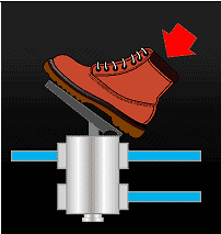 |
| Note the pressure indicated on the primary and secondary air tank gauges. | 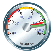 |
| Note the change in pressure over one minute. |  |
| Type of vehicle | Maximum allowable air loss |
|---|---|
| Straight truck, tractor or bus | 21 kPa (3 psi) per minute |
| Tractor and trailer | 28 kPa (4 psi) per minute |
| Tractor and two or more trailers | 41 kPa (6 psi) per minute |
The tractor protection valve on a towing vehicle ensures that an air- loss problem in the trailer does not result in loss of air from the towing vehicle.
To test the tractor protection valve, the trailer supply valve must be closed (pulled out), the trailer service line must be disconnected, and the service brakes applied. No air should be exhausting from the trailer service line. If air exhausts from the service line, the tractor protection valve is defective.
| Ensure that the air brake system is within its normal operating pressure range. | 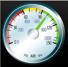 |
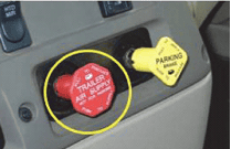
| Ensure the trailer supply valve is closed (pulled out). | 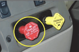 |
| Disconnect the trailer service air line coupler from either the trailer or the deadend coupler and place it where it can be observed. | 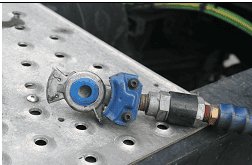 |
| Press and hold the brake pedal. (If there is a concern that the vehicle has no anti compounding valve, ensure the vehicle is secure and release the spring brakes before applying service brakes.) | |
| Observe whether air is exhausting from the trailer service-line coupler. | 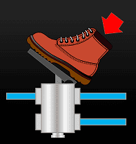 |
A trailer’s spring brakes must automatically apply whenever the trailer is disconnected from the towing vehicle. To test this, open (push in) the trailer supply valve to fully charge the trailer. Then pull out the trailer supply valve to close it. The trailer spring brakes should apply. Disconnecting the trailer air-supply line also activates this function, but closing the trailer supply valve is the recommended testing method. Brake application may be confirmed by gently applying engine power to move the vehicle forward or backward.
If the trailer spring brakes fail to apply automatically when the trailer supply valve is closed, the trailer brakes are defective.
| Ensure the trailer supply valve is open (pushed in) and the trailer is fully charged. | |
| Ensure the air brake system is within its normal operating pressure range. | |
| Pull out the trailer supply valve to close it. | |
| Observe the trailer for application of the trailer’s spring brakes. |  |
| If necessary, confirm brake application by attempting to gently move the vehicle forward or backward. |  |
A vehicle’s spring brakes must be capable of holding the vehicle in place. If the test is being conducted on a towing vehicle and trailer, select the vehicle on which to perform this test. It is preferable that this test be performed on the spring brakes of the towing vehicle. However, when a towing vehicle is pulling a trailer, it may not be possible to test its spring brakes separately. This can be done only on towing vehicle systems where the trailer can be supplied air while the parking brakes of the towing vehicle are released. Spring brakes can be tested by gently applying engine power in a low gear while the brakes are applied. The vehicle may rock slightly but the wheels should not turn during the test.
Failure of the spring brakes to hold the vehicle stationary indicates defective spring brakes.
| Apply the spring brakes on the vehicle to be tested and remove wheel chocks. | 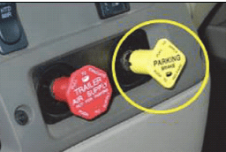 |
| Gently apply engine power in a low gear. |  |
| Observe the vehicle’s response. The vehicle may rock and shake and the wheels may move slightly, but there should be no significant movement of the vehicle. | |
Air tanks must be drained regularly, and the discharge observed for abnormalities. Some moisture may be discharged from the supply tank. A much smaller amount of moisture may be discharged from the remaining air tanks. A significant quantity of moisture being discharged from the supply tank – even when the tank is drained on a regular basis – may be normal. Discharge of a significant quantity of moisture from the remaining air tanks is not normal and should be reported.
While a small amount of oil may be found in the supply tank, any visible quantity of oil should be reported or repaired. When oil is found in any other air tank, there is risk of air brake system contamination, and the condition must be reported.
When there is a sudden increase in the amount of moisture or oil drained from any tank, the condition must be reported and repaired. Any malfunctioning drain valve must be repaired.
The supply tank should always be drained first to prevent accumulated moisture in the supply tank passing farther into the system. Drivers must know the location of all air tanks and drains.
It is important to note that the body design and suspension of some vehicles may limit safe access to the air tanks and drains unless the vehicle is supported on a hoist, or is over a pit or ramp.
| Ensure that the air brake system is within its normal operating pressure range. | |
| Locate and drain the supply tank until the valve discharges only clean air. | 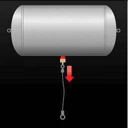 |
| Locate and drain the remaining air tanks. | 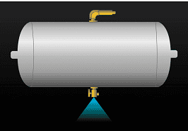 |
| Watch the discharge from each air-tank and ensure that all air-tank drain valves function properly. |