• Subscribe For Latest Update

Inspecting Air Brake Adjustment

1. Brake Adjustment must be Inspected Regularly

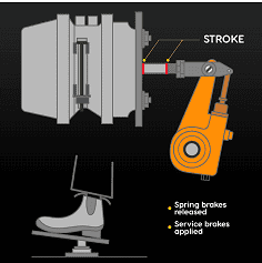
The pushrod stroke of each brake chamber is critical to the proper function of a brake system. As the brakes wear, brake pushrod stroke increases. Brake wear occurs at varying rates, depending on the type of vehicle and driving conditions. To determine whether brake adjustment is correct, the pushrod stroke must be inspected at least daily. When the brake pushrod stroke exceeds the adjustment limit, the brake is out of adjustment.
Brake pushrod stroke must comply with the Ontario Highway Traffic Act and regulations. Each air brake chamber’s pushrod stroke must not exceed the specified adjustment limits.
Since adjustment limits vary depending on the size and type of air brake chamber, you must be able to identify the particular brake chamber in use. Brake chamber size can be determined by measuring the diameter of the clamp used to hold it together or by locating the size markings on the brake chamber.
The most common brake chamber size is 30. However, there are vehicles using both smaller and larger sizes. For example, sizes 16, 20, 24 and 36 brake chambers may be used.
Measuring the diameter of brake chambers requires a special tool. Locating and reading the size markings on a brake chamber may require removing dirt, corrosion and paint from the surfaces.
You are most likely to determine the size of the brake chambers on any vehicle through your employer or the vehicle owner’s manual. This will avoid the need to measure a brake chamber or locate size markings. The type of brake chamber also affects the specified brake adjustment limit, which can vary by 19 millimeters or more between standard and long-stroke brake chambers. Long-stroke brake chambers can be identified by three visible characteristics:

  • The air lines attach to a square port in the brake chamber body.
  • A trapezoidal tag is placed under the clamp bolt that indicates the brake chamber’s maximum stroke dimension. (Not the brake adjustment limit.)
  • Markings are placed on the brake chamber body to indicate that it is a long-stroke brake chamber, and only long-stroke diaphragms are to be used as replacements.

The most visible and permanent of the markings used to identify long-stroke brake chambers are the square ports. Standard brake chambers have round ports.
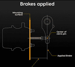
It is critical to use correct inspection methods to obtain reliable inspection results. The most reliable method for inspecting brake adjustment is to measure the applied pushrod stroke.

2. Step-by-step Procedure for Measuring Applied Pushrod Stroke

It is important to note that the body design and suspension of some vehicles may limit safe access to certain brake components unless the vehicle is supported on a hoist or is over a pit or ramp. Also, some brake systems have covers or housings that conceal the brake linkage, making it impossible to inspect brake adjustment using the techniques described here.

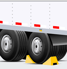
Secure the vehicle with wheel chocks or blocks The image illustrates a semi-truck's dual rear wheels securely chocked with yellow wheel chocks, ensuring the vehicle remains stationary. The chocks are placed snugly against the tires on a concrete surface. The side of the truck's white trailer is partially visible, detailed with red and white reflective tape for increased visibility and safety.
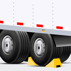
Ensure air pressure is above 621 kPa (90 psi) and release the spring brakes. The image depicts a truck air pressure gauge with the needle pointing at 90 PSI, which is also indicated in kilopascals as approximately 600 kPa. The gauge features a multicolored scale with zones marked in red, yellow, and green, symbolizing different levels of air pressure safety and efficiency.
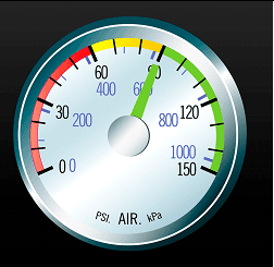
Select one of the following methods:
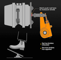
Method 1:
Mark the pushrod at the brake chamber or at a suitable fixed reference point. (Use chalk, soapstone, marker or other similar instrument – marks must be narrow and precise.)

The image displays an instructional diagram for measuring the stroke of a push rod in a vehicle's brake system. It shows a detailed side view of a brake assembly, including the brake pads, rotor, and an orange-colored actuator. A red arrow points to a specific spot on the push rod, indicating where to mark for measurement when the spring brakes are released and the service brakes are not applied.
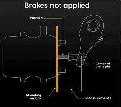
Method 2:
Measure the released position of the pushrod. Measure and note the distance from a point on the pushrod to a suitable fixed point at the brake chamber. This is Measurement 1.
The image is a schematic representation of a brake assembly in a non-engaged state, labeled
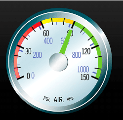
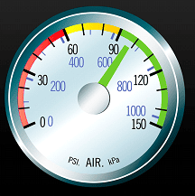
Raise or lower the air pressure by running the engine or pumping the brake pedal until both the primary and secondary air-tank gauges display 621 to 690 kPa (90 to 100 psi). The image depicts a truck air pressure gauge with the needle pointing at 97 PSI, which is also indicated in kilopascals as approximately 669 kPa. The gauge features a multicolored scale with zones marked in red, yellow, and green, symbolizing different levels of air pressure safety and efficiency.
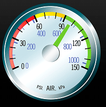
Shut off the engine. The image shows a close-up view of a person's hand turning an ignition switch on a truck's dashboard. The image is showing fingers grasping a small, round dial designed for ignition control. The dashboard around the switch is shaded in grey, focusing attention on the ignition dial and person’s hand.
Press and hold the brake pedal in the fully applied position. A diagram showing a boot pressing down on a foot valve in an air brake system. The foot valve is connected to blue air lines, indicating the flow of compressed air when the valve is activated. An arrow points to the heel of the boot, emphasizing the action of pressing the foot valve.
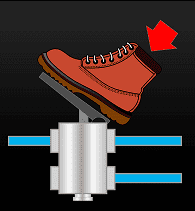
Method 1:
Measure the distance from the brake chamber or fixed reference point to the mark on the pushrod.
The image depicts a detailed diagram of a brake assembly showing the stroke measurement when the service brakes are applied and the spring brakes are released. It includes a side profile of the brake components such as the brake pads, actuator, and linkage. A red line marks the stroke length on the actuator, indicating the distance it travels when activated.
Method 2:
Measure the applied position of the pushrod. Remeasure and note the distance from the previously selected point on the pushrod to the previously selected fixed point at the brake chamber. This is measurement number 2. Subtract measurement 1 from measurement 2 to calculate the applied pushrod stroke measurement.
The image is a technical diagram illustrating the position of a brake system when the brakes are applied. It shows a side view of a brake mechanism, including the pushrod connected to a clevis pin. A red line highlights the center of the clevis pin, which is a critical point for measuring the stroke or movement of the pushrod during brake application. An orange line represents
Determine the number size (such as 16, 20, 24 or 30) and type (such as standard or long-stroke) of the brake chamber. The image features a specialized measuring tool designed for assessing the stroke of brake chambers in heavy-duty vehicles. This precision instrument, crafted from stainless steel, includes a curved arm and a built-in ruler with graduated markings to provide accurate measurements. It is essential for ensuring that the stroke within the brake chamber is within specified limits, which is critical for the safe operation of air brake systems in commercial vehicles.
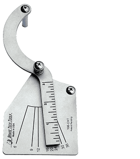
Determine the adjustment limit for the brake chamber. The image shows a brake adjustment measuring tool crafted from stainless steel, specifically designed for checking the adjustment limits of brake chambers in commercial vehicles. The tool features a curved arm with a pointed tip and a wide base where a detailed chart is engraved, listing the brake adjustment limits for different sizes and types of brake chambers. This chart provides essential data for technicians to ensure that brakes are within the safe operational thresholds, crucial for maintaining vehicle safety standards.
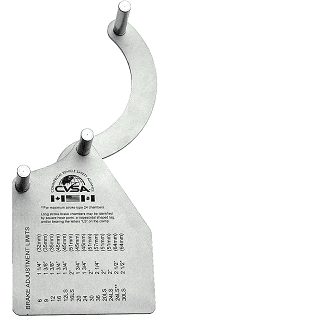
Compare the applied pushrod stroke to the applicable adjustment limit and identify any brake that exceeds the adjustment limit as defective.

Note: All drivers are required to demonstrate an applied pushrod-stroke measurement method for inspecting brake adjustment as part of the Ministry of Transportation air brake endorsement practical examination.

3. Using Brake Stroke Indicators

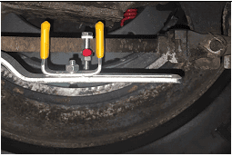
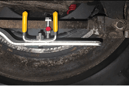
Brake stroke indicators are visual tools used to measure and monitor the movement of the brake pushrod in air brake systems. These indicators fit onto the brake linkage and fixed reference points near the brake linkage to provide a visual indication of the applied pushrod stroke. By using brake stroke indicators, drivers and maintenance personnel can efficiently check brake adjustment and identify potential issues without the need to get under the vehicle in many cases.

Step-by-step Procedure:

Prepare the Vehicle:

  • Park the vehicle on a level surface.
  • Apply the parking brakes.
  • Place wheel chocks or blocks around the wheels to prevent movement.
The image illustrates a semi-truck's dual rear wheels securely chocked with yellow wheel chocks, ensuring the vehicle remains stationary. The chocks are placed snugly against the tires on a concrete surface. The side of the truck's white trailer is partially visible, detailed with red and white reflective tape for increased visibility and safety.
Release Air Pressure:

  • Ensure that the air pressure in the brake system is above 621 kPa (90 psi).
  • Release the spring brakes by pressing the brake release button or lever.
The image depicts a truck air pressure gauge with the needle pointing at 90 PSI, which is also indicated in kilopascals as approximately 600 kPa. The gauge features a multicolored scale with zones marked in red, yellow, and green, symbolizing different levels of air pressure safety and efficiency.
Locate the Brake Chambers:

  • Identify the brake chambers on the vehicle where the brake stroke indicators are installed.
  • Ensure you have clear and safe access to view the brake stroke indicators and pushrods.
The image displays a brake stroke indicator tool in use, mounted within the wheel area of a vehicle to measure the stroke of the brake chamber. This tool includes a red marker and a caliper-style gauge with yellow handles, set against the backdrop of a brake drum, illustrating the real-world application and importance of precise brake measurement for safety.
Ensure Proper Installation:

  • Verify that the brake stroke indicators are securely attached to the pushrods and aligned with fixed reference points near the brake linkage.
Apply the Brakes:

  • Start the vehicle and build air pressure to the normal operating range (typically 621 to 690 kPa or 90 to 100 psi).
  • Apply the service brakes fully by pressing the brake pedal to its maximum travel position.
The image depicts a truck air pressure gauge with the needle pointing at 97 PSI, which is also indicated in kilopascals as approximately 669 kPa. The gauge features a multicolored scale with zones marked in red, yellow, and green, symbolizing different levels of air pressure safety and efficiency.
Observe the Indicators:

  • While the brakes are applied, observe the position of the brake stroke indicators on each pushrod.
  • The indicators will show the extent of pushrod travel. Compare the position of the indicator to the marked levels on the indicator device. The little red indicator slides back and forth. It should be between the two yellow goal posts.
The image displays a brake stroke indicator tool in use, mounted within the wheel area of a vehicle to measure the stroke of the brake chamber. This tool includes a red marker and a caliper-style gauge with yellow handles, set against the backdrop of a brake drum, illustrating the real-world application and importance of precise brake measurement for safety.
Determine Brake Adjustment:

  • Check the position of the brake stroke indicator against the manufacturer’s specified limits for the brake chamber size and type.
  • If the indicator shows that the pushrod stroke exceeds the acceptable range, the brake is out of adjustment and needs to be corrected.
Adjust Brakes if Necessary:

  • If any brake is found to be out of adjustment, follow the manufacturer’s procedure for adjusting the brake pushrod stroke.
  • Adjust the brakes to bring the pushrod stroke within the acceptable range.
Re-check After Adjustment:

  • After adjusting the brakes, reapply the service brakes and observe the brake stroke indicators again.
  • Ensure that the pushrod stroke is now within the acceptable range as indicated by the brake stroke indicators.
Final Steps:

  • Record the brake inspection and any adjustments made in the vehicle’s maintenance log.
  • Re-secure any components or covers that were removed during the inspection and adjustment process.

4. Automatic Slack or Brake Adjusters

Automatic slack adjusters, also known as automatic brake adjusters, are mechanical devices designed to maintain the proper clearance between the brake shoes and the drum in air brake systems. They automatically adjust the brake stroke as the brake linings wear, reducing the need for frequent manual adjustments. When properly installed and maintained, automatic slack adjusters are highly reliable and help ensure consistent braking performance.

Benefits of Automatic Slack Adjusters

Consistent Brake Adjustment:

  • Automatic slack adjusters continuously adjust the brake pushrod stroke to maintain optimal brake performance. This consistency helps prevent issues related to brake misalignment or improper adjustment.

Reduced Maintenance:

  • By automatically compensating for brake wear, these adjusters reduce the frequency of manual brake adjustments, saving time and reducing maintenance costs.

Enhanced Safety

  • Properly adjusted brakes improve overall vehicle safety by ensuring efficient and reliable braking performance, especially under varying driving conditions.

Compliance with Regulations:

  • Automatic slack adjusters help ensure that the brake system remains within the legal adjustment limits, aiding compliance with safety regulations and standards.

Inspection and Maintenance

Despite the advantages of automatic slack adjusters, regular inspection of brake adjustment is still necessary. Both automatic and manual slack adjusters require periodic checks to ensure they function correctly and maintain proper brake adjustment.

Re-adjusting brakes

When brakes with manual slack adjusters are out of adjustment, they must be readjusted so that the pushrod stroke is less than the adjustment limit. Only certified technicians may repair and perform brake re-adjustments on manual slack adjusters. In Ontario, drivers can become certified to perform brake re-adjustments on manual slack adjusters. Only those who have obtained certification are permitted to perform brake re-adjustments. This certification does not permit you to manually re-adjust automatic slack adjusters.
Automatic slack adjusters, if they are working properly, do not require regular readjustment. If periodic re-adjustments are required, it means that the automatic slack adjuster is defective and must be repaired by a certified technician. Only certified technicians are permitted to perform re-adjustments or repairs on automatic slack adjustors. It is dangerous for someone who is not certified to attempt to adjust the automatic slack adjustors. You may unknowingly damage the brake and cause it to malfunction. Check your automatic slack adjusters often to ensure that the adjustments are correct; however, do not attempt to repair them yourself.
Important: The Ontario Highway Traffic Act and regulations prohibit the operation of a vehicle with a brake that is out of adjustment.

Understanding the Appropriate Response to Defective Air Brake System and Component Conditions

An air brake system is a critical component of heavy vehicles, ensuring safe and effective braking performance. The Ontario Highway Traffic Act and its regulations strictly prohibit the driving or operation of a vehicle on a highway if its air brake system is defective. This legal framework emphasizes the importance of maintaining a fully functional brake system to ensure road safety.

Key Points:

Prohibition of Driving with Defective Brakes:

  • Under the Ontario Highway Traffic Act, it is illegal to drive or operate a vehicle with a defective air brake system. This regulation helps prevent accidents caused by brake failures.

Identification of Defective Conditions:

  • Drivers and maintenance personnel must be able to identify signs of defective air brake systems. Common indicators include abnormal sounds during braking, reduced braking efficiency, and visible damage or wear to brake components.

Mandatory Inspections and Maintenance:

  • Regular inspections of the air brake system are required to ensure all components are in proper working order. This includes checking for correct brake adjustment, ensuring there are no air leaks, and verifying the condition of brake chambers, hoses, and connections.

Immediate Action for Defective Brakes:

  • If a defect is identified, immediate action is required. This means taking the vehicle out of service until the issue is repaired. Continuing to operate a vehicle with known brake defects is not only illegal but also endangers the driver and others on the road.

Driver Responsibility:

  • Drivers must be knowledgeable about the air brake system and competent in performing daily inspections. They should be trained to recognize defective conditions and understand the appropriate steps to take if defects are found.

Reporting Defects:

  • Drivers must report any identified defects to their employer or the relevant maintenance personnel. Detailed records of inspections and repairs should be maintained to demonstrate compliance with safety regulations.

Legal Consequences:

  • Operating a vehicle with a defective air brake system can result in legal penalties, including fines and points on the driver’s license. In severe cases, it could lead to vehicle impoundment and suspension of driving privileges.

Ensuring Compliance:

  • Employers must ensure their fleet complies with the Ontario Highway Traffic Act by implementing regular maintenance schedules and training programs for drivers. Regular audits and compliance checks can help identify potential issues before they become serious problems.